Date: 2001-11-29
Author: Cam Finnigan
Thursday November 29, 2001 marked last year’s Technical Session, held at the Cambie Road location of Don Docksteader Motors. Our host for the evening was Jason Leber, Volvo Master Technician. The evening was attended by about two dozen members. Jason’s presentation was like a walk down memory lane, from low-tech to high-tech. In some ways, the evening was an continuation of Jason’s presentation at the meet this past August. Jason has been with Docksteader Motors for 7 years and previously worked for an independent Volvo repair shop in North Vancouver. He holds the title Technical Specialist.
Ten years ago, most of us were unaware of carbon monoxide (CO), carbon dioxide(CO2), nitrogen oxides (NOx), and hydrocarbons (HC). Now, with AirCare emissions standards testing, many of us have become all too familiar with these terms. The first part of the evening dealt with fuel and ignition systems. Four living demonstration cars were displayed and tested using an exhaust gas analyzer (EGA).
The second part of the evening covered car electrical systems, and in particular, new Controller Area Networks or CAN systems. Automotive electrical systems have changed more than anything over the last 30 years. This section will be covered in a future edition of the newsletter.
All of us know and love the simplicity of the older cars. Practically anyone could understand and work on the fuel, ignition and electrical systems. They were reasonably reliable, produced acceptable performance results and could be fixed or adjusted at the side of the road with a pocket full of tools. And, there were lots of adjustments to play with. But, times have changed. All of the systems have changed and now it requires a whole new level of tools and understanding to diagnose and repair the new systems. Many of you have probably said, “Things just aren’t like they used to be”, or “I remember when…” Influences that have driven the change include the reduced cost of highly integrated digital electronic control systems (sometimes called MCU, ECU, computer, control module), increasingly stringent emissions regulations, and customer demands.
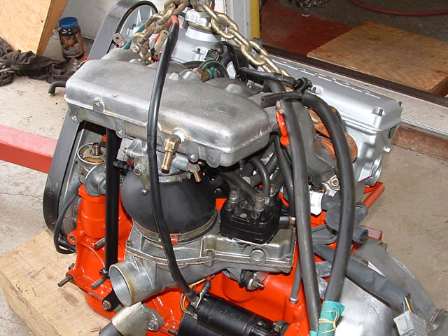
We looked at four cars of varying ages and levels of complexity. The first was a 1980 DL wagon with a B21A. This was the simplest of the four. It featured an SU carburetor, points and capacitor ignition. This was the most basic Volvo of this year. The next vehicle was a 1982 GL with a B23E. This was the same generation as the 1980, but a slightly more advanced car. All GL, GT, GLE, Turbo and GLT of this era use Bosch K-Jetronic fuel injection and (normally) Bosch electronic ignition. I can speak from experience that this setup is extremely reliable. The next was a 1990 740 with a 16 valve B234F engine, LH-Jetronic 2.4. This fuel system uses feedback in the form of an oxygen (O2) sensor, and pulsed injection. The fourth and most advanced car was an S70, with a five cylinder engine and sequential fuel injection.
Using the exhaust gas analyzer (EGA), Jason demonstrated the improved emissions over the years that the four cars were made. The first car, the 1980 DL produced the most CO, by far. CO is a product of incomplete combustion and is itself a fuel. If you starve fuel of oxygen (too rich) then you end up with an increased level of CO. This means that your fuel is not being put to the best possible use and has not completely burned. The DL produced 3.6% CO. The distributor functions to control the primary of the ignition coil and select the appropriate cylinder for spark. It takes care of absolute timing, timing advance and dwell.
The second car, the GL, turned out better emissions results with 1.4% CO and 100 ppm (parts per million) HC. This K-Jetronic system first showed up around 1974 or 1975 and became much more popular in the 1980s. It is completely mechanical and produces a continuous injection of fuel into the airflow just outside of the intake valve. The ignition system uses no points instead a “no touch” pickup in the distributor. This connects to the ignition module which controls a conventional ignition coil. The spark is then distributed to the four cylinders using a rotor in the distributor. This system was discontinued in Volvos in 1984. It should be noted that the 264 and Turbo models had a variant of this system, sometimes referred to as Lambda or KE, thus the familiar Lambda symbol “λ” on the grille. It used an O2 sensor to complete a control loop in order to maintain the proper mixture. The balance of the system remained unchanged.
The 1990 740 was the first of the four to use a true “electronic” injection system, using a control module that is the “brains” of the system. This LH 2.4 system was the second LH system, the first being LH 2.2. LH 2.4 was first used in 1989 on all models except for Turbo, with the Turbo following in 1990. The LH 2.4 system came with a diagnosis centre, allowing service personnel and owners to play doctor when something goes wrong. The LH systems use an O2 sensor to regulate mixture and a catalytic converter to “finish off” any CO, HC and NOx. This results in very low emissions: 1 % CO and 20 ppm HC. The term LH comes from Lambda Hotwire. Air flow is measured by an air-mass meter, an instrument through which fresh intake air is drawn. Inside the air-mass meter is a heated platinum wire which is cooled in proportion to the air flowing over the wire. The signal is passed on to the ECU which controls the injectors.
The final car, and with the lowest emissions, was the S70. This vehicle makes use of two O2 sensors, one on each side of the catalytic converter, and falls into the category of Ultra Low Emissions Vehicle or ULEV. The second sensor does not play a role in mixture adjustment but merely acts as an alarm in the event of catalytic converter failure. Aside from a transient reading at startup, the emissions from this car leveled off at 0 and 0 for CO and HC. Jason notes that this is vehicle is the most complex electrically and had to be to achieve such high efficiency.
Pros and Cons
There are many opinions on the evolution of fuel, ignition and control systems on Volvos. On one hand, the older cars can virtually be repaired anywhere with only a handful of basic tools. There is no diagnostic connector on a 122! These systems were reasonably reliable and performed adequately. On the other hand, the newer cars are too complex for the average backyard mechanic to either understand or diagnose, apart from changing oil, brakes, tires… Parts for the new cars, although very reliable, tend to be costly. Service is likely to require highly specialized tools for diagnosis. There is virtually nothing to adjust except the position of the driver’s seat. So, what are the advantages? Lower emissions (AirCare subscribers like that), better fuel economy (one member claims his 3 litre 960 has the best fuel economy of any Volvo he has owned), better performance, built in diagnosis, ease of repair (by dealership). Certainly, eliminating adjustments simplifies the service process. On the Volvo S80 a major service consists of replacing the air filter and spark plugs, and vacuuming and washing the car.
Personally, I don’t miss the poor performance of my old 1980 DL B21A when compared to my 1980 GT B21F. Fuel injection and electronic ignition has given the car much more performance and lower emissions. Emissions are usually better than the carbureted cars, but in my case I am suffering from a faltering fuel distributor, so it’s only a matter of time before this needs to be replaced. The K-Jetronic system is quite reliable, but still there are components to fail. And, older systems can have vacuum leaks around the injectors and can be difficult to start once hot.
About Catalytic Converters
The catalytic converter is inserted in the exhaust stream a short distance from the engine. It’s purpose is to break down undesirable components of incomplete combustion: CO, HC and NOx. Converters are fed with exhaust which is nominally 0.5% CO, and reduces CO typically to near zero. The oxygen sensor is inserted into the system upstream from the converter and regulates the mixture to maintain as close as possible to 0.5% CO. The catalytic converter is filled with a catalyst such as platinum or palladium in a physical form which maximizes surface reaction area. They typically last 10 years or more but can be compromised by exhaust which is laden with oil or antifreeze or which is too rich. Volvo original equipment replacements are in the $1200 range. Would you also like that installed? You might be tempted to go for a cheaper replacement from an exhaust franchise. We were warned that you might be greatly disappointed by the shorter than expected life of inexpensive replacements. By the way, newer Volvos are equipped with three-way converters. Two-way converters do not treat NOx.
Hints and Tips
Jason pointed out that the Pulsair lines must be blocked (plugged) during adjustment, otherwise the mixture will end up being too rich.
Many of the older engines are prone to knocking while under load, especially when using lower grade fuels. Jason noted that the springs holding the advance weights inside the distributor become weak with age, allowing the timing to advance too far. This extra advance, combined with other factors, produces the undesired knocking.
Wax Thermostat from a Volvo 240 air box.
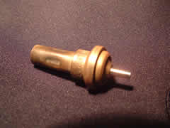
One of the common failures on the LH system is a faulty air-mass meter or a poor electrical connection to the unit. If the air-mass meter is faulty it may cause the car to stall immediately after being started. If the electrical connection to the air-mass meter is poor, you may experience very poor performance. This can be rectified by cleaning the electrical connection with WD-40 and repeatedly inserting and removing the connector. Complete failures are most frequently caused by excess intake air temperature. A mixing thermostat in the air box blends cool outside air with hot air taken from a heat exchanger on the exhaust system. If the thermostat fails it may deliver hot air only, thus damaging the air mass meter from the excess temperature. A new air-mass meter will run $500 or so, much more expensive than a $50 or $70 thermostat.
Oxygen sensor failures will almost always be brought to your attention at the exit lane of AirCare. Replacements are typically $350. There are two types: voltage producing and resistive.
LH 2.4 systems, starting in 1989 (1990 for Turbo models) come with a diagnosis centre. This small module, located close to the brake servo, has an indicator light and a small jumper which can be plugged into a number of sockets. Socket number 2 is used for fuel system diagnosis, 6 for ignition. If the air-mass meter has been disconnected (not a normal occurrence in driving, but possibly similar to a broken unit) then the associated code 1-2-1 will be flashed by the light once the jumper is plugged and the button pressed for one second. Successive codes can be read by simply pressing the button once after each code. The error codes are stored in a circular buffer, so eventually the first code will again be displayed. Once the first code has been presented again, the button is pressed for 8 seconds and then released. When the light comes on again, press and hold for another 8 seconds to clear the faults from the register. At this point, pressing the button again should reveal no fault codes. A complete list of fault codes can be found on a separate page.
Starting in 1998, legislation mandated the use of warning systems to indicate a breech in the fuel tank seal. Since the fuel tank is loaded with fuel vapours (HC) it is important to make certain that these vapour do not escape unnecessarily. They are normally absorbed by the evaporation control system. The tanks operate under slight pressure. So, when you stop by the fueling station, and the attendant cross-threads your fuel cap, you receive a warning light on your 1998 or newer Volvo. The sad news is that you now need a trip to the dealership to shut the light off.
In the newer models, 99% of all ” Check Engine ” light warnings are for emission faults or failures.
Cars certainly have changed over the years and nowhere in the car are the changes more significant than in the electrical and control systems. Jason gave a comparison between a 1960 122 and a 1998 S70. The 122 came with 7 fuses (that was a lot compared to 2 in most British sports cars of the era), 83 metres of wire and CO of between 3% and 5%. The S70 has evolved to 54 fuses, 1200 metres of wire and 0.5% CO (at the engine). What is the downside of this much wire? Cost (design and manufacture), installation time (more cost), weight (fuel cost to the owner), many connections (reliability and cost), and difficult fault tracing (cost). So, basically, it comes down to cost. Don’t forget that running all of those accessories such as rear window heater, headlights, seat heater, climate control and so on consumes electrical power. That power ultimately comes from fuel. Jason pointed out that an added load of 1 kW will cost you up to 1.7 litres extra per 100 km.
With more and more “things” in the newer car requiring control the number of electronic “controllers” has increased accordingly. Starting in 1999, a loaded Volvo S80 contains as many as 18 separate control units. These units are connected to a Controller Area Network or CAN system. This is not too dissimilar to the network that your computer at work might be connected to. It enables all of these modules to communicate with one another through a very simple medium using a special language. There are control modules in the instrument cluster, in the climate control, the radio, the rear lights and a dedicated system for the engine, automatic transmission, anitlock brake system and supplementary restraint system. There is no longer a headlight circuit running through your headlight switch, nor does the brake light wire run to your brake pedal. As scary as it may seem to some, there is no longer even a throttle cable! This control is strictly “drive-by-wire”. The throttle pedal attaches to a position sensor which is connected through the network and controller to a servo controlled throttle body. This item, oddly enough, resembles an old 35 mm SLR camera. Some of us thought we were going to have our pictures taken.
Each of these control modules has a tiny computer inside that is frequently referred to, at least in my industry, as an MCU. This controller is designed and built to carry out a specific function based on inputs from sensors and provides some form of output based on software (or technically “firmware”) which is commonly stored in Flash memory. These instructions are developed alongside the controller and are based on the desired functionality that the manufacturer wishes to achieve. The firmware is loaded to each module when the car is built. Each module has an indelible electronic serial number which uniquely identifies that part against all similar parts in other cars. When the car leaves the factory a record of the car is retained with the manufacturer identifying all of the modules that are contained in each car. The network communications protocol, message format and all decision algorithms are defined by this firmware. It is now possible to perform extremely complex tasks quickly and accurately at fairly low cost. Events can also be recorded and it is possible to have a controller “learn” so that future outcomes can be predicted by examining a record of previous outcomes.
The real beauty of controllers (and I know first hand) is that if you don’t like the results that your current firmware is giving you, then you go to the firmware team and ask for a new revision to correct the problem. The best part is that you don’t even have to open the cover. New firmware can be downloaded to the controller right over the network. This new firmware then replaces the old firmware and the controller then takes on new characteristics. The danger in upgrading firmware is that there is always a risk of being stuck in the event of an interruption in power or communications of the firmware. You may have erased the very firmware that will allow you to communicate further downloads. There are many ways of executing this download and designers normally build in some type of contingency against a total disaster.
Jason demonstrated a typically download into the automatic transmission control unit of a Cross Country using the Volvo Aftersales Diagnostic and Information System or VADIS . This looks a bit like a computer on a fancy shop cart. It comes with a really fancy price of about $60k. They currently have two, and given that they are nearly as essential as breathing, could use another one. Every time your car goes into the shop for an oil change, the VADIS is contacted to your car and scans your car for fault codes. In the case of the XC, the firmware was updated pro-actively to rectify a problem in the shifting algorithm that the customer may eventually complain about. The VADIS is a wealth of information. It also comes complete with parts information and step by step fault finding.
The VADIS communicates with the car, reads fault codes (if any), identifies the control modules and sends that information to the factory in Sweden. The factory then authorizes the download and 102 kilobytes of firmware is injected into the car through the OBD2 (On Board Diagnostic) connector, located between the front seats. This is an industry standard connector legislated for all manufactures to use. The same goes for the fault codes that the car communicates to the service computer. At the same time, the “adaption” is reset to zero. Now that the load is complete, the technician must then take the car out on the road for a series of specific exercises to retrain the adaption.
As a result of controller serial numbers and the possibility of having non-compatible firmware, it is no longer acceptable to buy used network components from the wrecker and expect them to work normally in your car. The next time the car is connected to VADIS, the question, “What are you doing in this car?” will arise.
Intermittent faults can result in the warning light going on and then off. Some faults, if occurring only once, will eventually extinguish the warning light after a number of driving cycles without any error. These faults will still be recorded in the controller and can be read out by the shop.
So, like it or not, your new car now comes complete with an array of computers that help with cost, serviceability and functionality. These are not too dissimilar to the small controllers that you find in your modern TV, VCR, furnace, cell phone, bread maker and child’s toy. This really is the future of most products that are electronic or require intelligence. If you are uncomfortable with this concept then perhaps new cars are not for you.
System Fault Codes
The following is a table of system fault codes (Diagnostic Trouble Codes or DTC) from newer LH Jetronic Systems. A complete explanation of retrieving these codes can be found in the 2004 Technical Session.
For those readers unfamiliar with the code flashing sequence on this system, have a look at this short video clip. Here, you will see the code pattern 2-3-2 displayed by the red LED. As can be seen in the table below, it indicates “Adaptive fuel trim too lean or too rich at idling.” On this particular vehicle, there happened to be two fault codes present, the second one being 2-1-2, “HO2S signal absent or faulty.” A description of how to retrieve the codes can be found below the tables.
You can Search and Sort in this table.
| DTC | Fault message |
|---|---|
| 1-1-1 | No fault detected |
| 1-1-2 | Control module fault |
| 1-1-3 | Short term fuel trim (Lambda control) too lean/rich |
| 1-2-1 | MAF sensor signal absent or faulty LH 2.4 |
| 1-2-1 | MAF sensor signal absent or faulty LH 3.1 |
| 1-2-3 | ECT signal absent or faulty |
| 1-3-1 | Engine speed signal from 01 system absent on starting |
| 1-3-2 | Battery voltage too low or too high |
| 1-3-3 | TP switch signal faulty at idling LH 2.4 |
| 2-1-2 | HO2S signal absent or faulty |
| 2-1-3 | TP switch signal faulty at full load LH 2.4 |
| 2-2-1 | Adaptive fuel trim too lean in part-load range |
| 2-2-3 | IAC valve signal absent or faulty |
| 2-3-1 | Adaptive fuel trim too lean or too rich in part-load range |
| 2-3-2 | Adaptive fuel trim too lean or too rich at idling |
| 3-1-1 | Speedometer signal absent |
| 3-1-2 | No knock enrichment signal from 01 system |
| 3-2-2 | MAF sensor burn off signal absent or faulty LH 2.4 |
| 4-1-1 | Throttle position sensor signal absent or faulty LH 3.1 |
| DTC | Fault message |
| 1-1-1 | No fault detected |
| 1-4-2 | Control module fault |
| 1-4-3 | KS signal absent or faulty |
| 1-4-4 | Load signal from MFI system absent |
| 1-5-4 | EGR system flow too high |
| 2-1-4 | RPM sensor signal absent intermittently |
| 2-2-4 | ECT sensor signal absent or faulty |
| 2-3-4 | TP switch signal in idling position faulty |
| 2-4-1 | EGR system flow too low (NTC) |
| 2-4-1 | EGR system flow too low (PTC) |
| 4-1-3 | EGR temperature sensor signal absent or faulty (NTC) |
| 4-1-3 | EGR temperature sensor signal absent or faulty (PTC) |
| Glossary | |
| MAF | Mass Air Flow |
| EGR | Exhaust Gas Recirculation |
| ECT | Engine Coolant Temperature |
| TP | Throttle Position |
| KS | Knock Sensor |
| HO2S | Oxygen Sensor |
| IAC | Idle Air Control |
| RPM | Revolutions/Minute, often called engine speed sensor, but more technically correct would be crankshaft position sensor |
Glossary:
MAF: Mass Air Flow | EGR: Exhaust Gas Recirculation | ECT: Engine Coolant Temperature | TP: Throttle Position | KS: Knock Sensor | HO2S: Oxygen Sensor | IAC: Idle Air Control | RPM: Revolutions/Minute, often called engine speed sensor, but more technically correct would be crankshaft position sensor
Retrieving Fault Codes
Diagnostic Interface in a 940 TurboDiagnostic Interface in a 940 Turbo
Locate the diagnostic service interface. This is a little black plastic box located near the shock tower on the driver’s side engine bay. This varies slightly from model to model. The protective cover must first be removed.
Turn the ignition switch to the ON position, but do not start the car.
Locate the jumper lead (the plug stores in a pocket in the cover) and insert it into the socket number 6. Press the diagnostic button on the interface for about a second and a half, about the time required to say “Volvo Corporation”.
The LED will begin flashing, with the flashes representing diagnostic codes. Flashes are presented in three groups of flashes (approximately 0.5 seconds), separated by a slightly longer interval: first, second and third, representing the first, second and third digit of a three-digit code. Have a look at this short video showing the LED flashing.
If the code presented is 1-1-1, that means that the register is empty and there are no fault codes stored. A non-1-1-1 fault code represents a specific trouble, which can be decoded using the associated table.
After a fault code has been recorded, press the button again, saying “Volvo Corporation”.
The next code is displayed or, if there are no more codes, the first code is displayed again.
When all of the codes have been recorded, the buffer can be erased by first pressing and holding the button for five seconds and then releasing it.
After a brief pause, the LED should again light. Press and hold the button for an additional five seconds and then release. The LED should go out.
System Overview – System Components
The fuel system consists of an air mass meter, commonly referred to as MAF sensor, an oxygen sensor, a throttle body, fuel injectors (one per cylinder) and a catalytic converter.
The Mass Air Flow (MAF and often referred to as air mass meter) is responsible for measuring instantaneous airflow into the engine. In LH, the MAF consists of a wire that is heated with an electrical current and cooled in proportion to the air flowing over it. The sensor measures how much power is required to keep the hot wire at its prescribed temperature and that tells the fuel management system how much air is flowing into the engine. The wire should remain clean so, when the engine is turned off a relay is activated for a preset time and the wire is super heated to burn off any dirt.
The Heated Oxygen Sensor (H02S), located in the hot exhaust gas stream, analyses the gas content of the exhaust and reports the content to the control computer. This sensor operates only above a certain temperature and therefore its readings are disregarded for a short period of time following engine startup.
The Throttle Body is the fuel injection equivalent of the throttle in a carburetor. It is responsible for regulating the flow of air (and therefore the flow of fuel) into the engine. The idle switch signals the computer when the throttle is closed and the Idle Air Control (IAC) valve should be activated.
The Idle Air Control valve is an electronically controlled valve that allows relatively small amounts of intake air into the engine. This is used only when the idle switch on the throttle body signals that the throttle is closed. This system allows the engine control computer to maintain a precise idle speed regardless of engine condition and load.
The Throttle Position Sensor, or TPS, is located on the throttle body at one end of the throttle shaft. It signals the computer when the throttle is either closed (IAC can be activated) or fully open.
The Fuel Injectors, not surprisingly, inject fuel into the stream of intake air, normally immediately before the intake valve.
The Fuel Pressure Regulator maintains a precise fuel pressure on the fuel rail supplying the injectors. The fuel pump attempts to deliver fuel at a fixed rate, so the excess is returned to the fuel tank via a dedicated return line.
The Catalytic Converter is an element of the exhaust system located relatively close to the engine. It is responsible for breaking down the unwanted by-products of combustion, such as carbon monoxide, hydrocarbons and nitrogen oxides.
The Coolant Temperature Sensor monitors the temperature of the engine coolant and thus the operating temperature of the engine.
The Engine Speed Sensor (ESS), Impulse Sensor or RPM sensor is a sensor that actually determines the position of the crankshaft as it rotates. The sensor is more correctly named the Crankshaft Position Sensor, as speed can be derived from angle, but angle cannot be derived from speed. This sensor is responsible for synchronising fuel and ignition.